Panduan Wiring Diagram untuk Perangkat IoT Circuit Diagram Find every electronics circuit diagram here, Categorized Electronic Circuits and Electronic Projects with well explained operation and how to make it procedure and then New Circuits every day, Enjoy and Discover electronics. Wi-Fi modules for wireless iot projects. December 22, 2015.
Whether you're a hobbyist, DIY enthusiast, or professional engineer, our resources provide comprehensive guides, tutorials, and circuit diagrams to help you integrate wireless technology seamlessly. Explore the possibilities of remote control systems, IoT devices, wireless sensors, and more with our expertly curated selection.

Fi modules for wireless iot projects Circuit Diagram
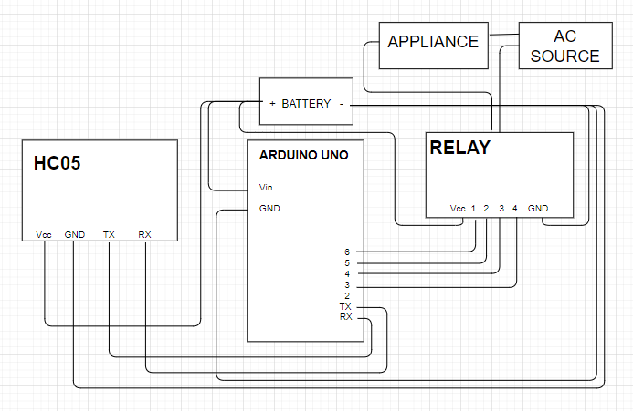
The diagram below provides a general visual reference for wiring of the components once you get to the Assembly page. This diagram was created using the software package Fritzing.

Wi-Fi Smart Switch Circuit Diagram. Testing Wireless Smart Switch. CONCLUSION. Hammond's modern 1556 series enclosures are designed for circuit boards and IoT equipment. WRIS-RSKS Series General-Purpose Thick-Film Resistors. General-purpose thick-film, anti-sulfur resistors designed for long-term performance and reliability Explore simple IoT Projects on Home Automation, Internet of Things using Arduino, ESP8266, ESP32, ESP32 CAM, LoRa for engineering students. All projects explained with source code, circuit diagram, woking principle. In the IoT, sensors in remote locations and smart homes leverage wireless power for seamless operation. Industrial automation and robotics witness increased efficiency through wirelessly powered sensors and actuators. So it is beneficial to experiment wireless power transfer techniques. Circuit Diagram
ESP8266 WiFi Projects Circuit Diagram
Here is the simple Wireless Power Transmitter and Receiver Circuit Designed with few affordable electronic components. Both Transmitter and Receiver have Enameled Copper coil winding, A Square wave oscillator and copper coil acts as power transmitter. Copper coil and Bridge Rectifier circuit acts as Receiver. Internet of Things (IoT) is revolutionizing the electronics industry. All projects are documented with a neat circuit diagram, code and demonstration video to provide a complete do-it-yourself experience. Hammond's modern 1556 series enclosures are designed for circuit boards and IoT equipment. WRIS-RSKS Series General-Purpose Thick
Including circuit diagram and detailed working explanation. 100% working and tested circuits. Sending E-mail from ESP8266 - IoT Project The scope of the IoT applications is growing from controlling appliances to monitoring devices (like sensors) and sending e-mails.